

Load Cell Guide: Types, Working Principle, Installation, and Calibration
What Is a Load Cell?
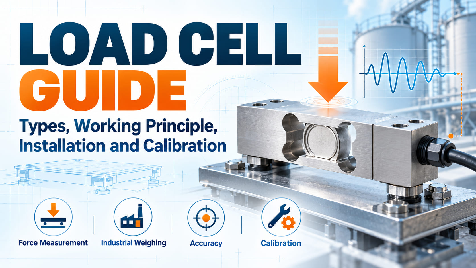
A load cell is a transducer used to convert mechanical force into a measurable electrical signal. In practical applications, the force may come from weight, compression, tension, pulling force, structural loading, or a combination of these conditions. The output from the load cell can then be processed by an indicator, transmitter, controller, PLC, data acquisition system, or weighing instrument.
The most common industrial load cell uses strain gauge technology. Strain gauges are bonded to a carefully designed metal sensing element. When force is applied, the element deforms by a very small amount. The strain gauges detect that deformation as a change in electrical resistance. A Wheatstone bridge circuit converts the resistance change into a small electrical output that is proportional to the applied load.
Simple principle: mechanical force → elastic deformation → strain gauge resistance change → electrical signal → displayed force or weight value.
Load cells are commonly found in platform scales, hopper scales, tank weighing systems, filling machines, packaging lines, material testing equipment, crane scales, industrial presses, robotic equipment, batching systems, silos, force test stands, and production monitoring systems. They can be designed for forces ranging from very small laboratory measurements to extremely large industrial loads.
Who Uses Load Cells?
Load cells are useful for engineers, machine builders, system integrators, automation companies, weighing equipment manufacturers, laboratory technicians, process engineers, quality control teams, and industrial operators. They are especially valuable whenever a machine needs to know how much weight or force is being applied rather than relying only on movement, position, pressure, or visual inspection.
Why Is a Load Cell Needed?
A load cell is needed whenever accurate force or weight information must be converted into data that a machine or operator can use. In many industrial processes, knowing that an object is present is not enough. The system must know how heavy the object is, how much material has entered a tank, how strongly a component is being pressed, or whether a mechanical structure is being overloaded.
Industrial Weighing
One of the most common load cell applications is industrial weighing. Platform scales, floor scales, truck scales, hopper scales, and tank systems use one or more load cells to convert physical weight into a digital value. This allows operators to monitor inventory, shipping quantities, production weight, or material consumption.
Batching and Filling
In batching and filling applications, a load cell allows a controller to determine when the correct amount of material has been added. For example, a mixing system may fill a vessel until the measured weight reaches a programmed setpoint. This approach is often more direct than estimating quantity from time, volume, or flow alone.
Force Testing and Quality Control
A load cell is also used to measure pressing force, pulling force, insertion force, clamping force, breaking force, or assembly force. Manufacturers can use this data to verify whether a component meets design specifications or whether a production process is operating within acceptable limits.
Safety and Overload Monitoring
Load measurement can also contribute to machine protection. Cranes, lifting devices, presses, structures, and material handling systems may use load cells to identify excessive force before equipment is damaged. The load cell does not replace proper mechanical safety design, but it can provide valuable feedback for alarms, shutdown logic, or maintenance monitoring.
Common Types of Load Cells
Load cells are available in many mechanical designs because different machines apply force in different ways. Selecting the right type is important because a sensor designed for one loading direction may perform poorly or be damaged when used incorrectly.
Single-Point Load Cell
A single-point load cell is commonly used in bench scales, counting scales, retail scales, and small platforms. Its mechanical design can compensate for moderate off-center loading within a specified platform size. This makes it useful when the object being weighed cannot always be placed exactly in the center.
Shear Beam Load Cell
Shear beam load cells are widely used in platform scales, hopper systems, conveyor weighing, tank weighing, and industrial machinery. They offer a practical combination of mechanical strength, accuracy, and installation flexibility.
Bending Beam Load Cell
Bending beam designs are often used for moderate capacities and applications where the load cell must provide stable measurement in a compact installation. Depending on the model, they can be suitable for process weighing, machinery, filling systems, and industrial platforms.
S-Type Load Cell
The S-type load cell is named after its shape and is frequently used for both tension and compression measurement. It is common in hanging scales, material testing, force measurement, suspended hopper systems, and test machines.
Compression Load Cell
Compression load cells are designed to measure forces pushing into the sensor. They are frequently used in high-capacity weighing, large vessels, industrial presses, structural testing, and heavy-duty machinery.
Tension Load Cell
Tension load cells measure pulling force. They may be used in cable tension monitoring, lifting systems, suspended weighing, material testing, or applications in which the sensor is installed in line with a tensile force.
How to Select and Use a Load Cell in 5 Steps
Choosing a load cell should not begin with capacity alone. A sensor with the correct maximum load can still produce poor results if the mounting method, environment, loading direction, electrical output, or accuracy requirements are unsuitable. The following five-step process provides a more complete selection method.
Step 1: Define the Measurement Range
Determine the normal working load, maximum expected load, dead load from fixtures or platforms, and any potential shock or overload. The rated capacity should provide appropriate operating margin without being excessively oversized. A load cell that is far larger than necessary may reduce useful signal resolution for small measurements.
Step 2: Identify the Loading Direction
Decide whether the application is compression, tension, or both. Also consider side force, bending moment, torque, vibration, and misalignment. Load cells are designed to perform best when force enters the sensor along the intended load axis. Unwanted side loading can increase error and may shorten service life.
Step 3: Check Accuracy and Signal Requirements
Review the required system accuracy, repeatability, linearity, hysteresis, creep, and temperature behavior. Also confirm the electrical interface. Traditional strain gauge load cells often provide a low-level millivolt-per-volt output and therefore require stable excitation and appropriate signal conditioning. Some systems use integrated transmitters to provide amplified analog or digital signals.
Step 4: Evaluate the Environment and Mechanical Installation
Temperature, washdown, humidity, chemicals, dust, vibration, corrosion, outdoor exposure, and cable routing can all affect system reliability. The mounting surface must also be rigid enough to transfer force correctly. Poor mechanical installation can create measurement problems even when the load cell itself is high quality.
Step 5: Install, Calibrate, and Verify the Complete System
After installation, connect the load cell to the appropriate indicator or controller and perform system calibration according to the equipment design. Check zero stability, span, repeatability, corner loading where relevant, and response under known test loads. Calibration should evaluate the complete installed system rather than assuming the sensor alone determines measurement quality.
Load Cell Selection Comparison Table
| Load Cell Type | Typical Load | Common Applications | Key Selection Point |
|---|---|---|---|
| Single-Point | Compression | Bench scales, platform scales, counting scales | Check allowable platform size and off-center load performance |
| Shear Beam | Mostly compression | Hoppers, tanks, industrial platforms, conveyors | Use correct mounting hardware and control side forces |
| Bending Beam | Compression or specialized loading | Process weighing, filling machines, machinery | Verify mounting orientation and rated capacity |
| S-Type | Tension and compression | Force testing, hanging scales, suspended systems | Maintain axial alignment and avoid bending |
| Compression | Compression | Heavy weighing, presses, structural testing | Ensure flat loading surfaces and stable force transfer |
| Tension | Tension | Cable force, lifting, suspended weighing | Use suitable connectors and prevent off-axis pull |
Common Load Cell Mistakes to Avoid
Even a correctly specified load cell can produce poor results if the surrounding system is designed incorrectly. These mistakes are especially common during machine integration and custom weighing projects.
1. Selecting Capacity Without Considering Dead Load
The load cell must carry not only the product being measured but also platforms, containers, fixtures, structural components, and other permanent loads. Ignoring dead load can consume too much of the available measurement range.
2. Oversizing the Load Cell Too Much
A very high-capacity load cell may survive the application, but the useful measurement signal can become unnecessarily small when normal operating loads occupy only a tiny portion of rated capacity.
3. Ignoring Side Loads and Misalignment
Load cells are generally most accurate when force follows the intended measurement axis. Side loads, torque, bending, binding pipework, rigid cables, or uneven mounting can introduce additional forces that affect the reading.
4. Using the Wrong Load Cell for the Environment
Moisture, washdown, chemicals, outdoor exposure, dust, and temperature variation can damage an unsuitable sensor. Environmental protection, materials, sealing method, cable design, and installation location should all be checked.
5. Treating Calibration as a One-Time Task
Systems can change because of mechanical wear, mounting changes, environmental conditions, repairs, impact, or process variation. Appropriate verification and recalibration intervals should be established according to the accuracy needs and operating conditions.
6. Neglecting Cable and Electrical Noise Issues
Because strain gauge load cell outputs can be very small, poor grounding, electrical noise, inappropriate cable routing, unstable excitation, and unsuitable signal conditioning may affect measurement stability.
Advanced Load Cell Best Practices
Use Mechanical Overload Protection
If the machine may experience accidental impact, product jams, shock loading, or operator misuse, consider mechanical stops or other overload protection. A load cell may have overload capability beyond its rated capacity, but repeated or severe overloading can permanently change its zero point or damage the sensing element.
Design the Structure Around the Load Path
Accurate load measurement depends on where force actually travels through the machine. Flexible frames, binding pipes, mechanical friction, uneven supports, and contact with surrounding structures can bypass or distort the intended load path. Good structural design ensures that the force to be measured passes through the load cell in a predictable way.
Allow Time for Stabilization
In dynamic processes, the reading may move because of vibration, product motion, sloshing liquid, mechanical shock, or machine movement. Filtering can improve displayed stability, but excessive filtering may slow response. The correct balance depends on whether the application prioritizes fast response or stable weight indication.
Evaluate the Entire Measurement Chain
A high-accuracy load cell does not automatically create a high-accuracy system. Excitation stability, amplifier quality, analog-to-digital conversion, mechanical installation, temperature changes, wiring, calibration method, software filtering, and structural behavior all contribute to final measurement performance.
Keep Installation and Calibration Records
Record the load cell model, capacity, serial number, wiring, mounting arrangement, calibration date, calibration results, and maintenance history. These records make troubleshooting easier when measurement behavior changes after equipment service, relocation, impact, or component replacement.
Conclusion and Next Step
A load cell is one of the most important sensing components in modern weighing and force measurement systems. It transforms mechanical force into an electrical signal that can be displayed, recorded, analyzed, or used for automated control. However, choosing the correct load cell requires more than matching the maximum weight.
Capacity, dead load, tension or compression direction, side forces, accuracy, mounting, environmental conditions, output signal, overload risk, and calibration requirements should all be considered together. A well-designed system also controls the load path, protects the sensor from unintended forces, and verifies performance after installation.
Next Step: Before requesting a load cell quotation, prepare the required capacity, minimum measurement range, loading direction, mounting space, operating temperature, environmental conditions, desired output signal, and target system accuracy. Providing these details helps narrow down the correct sensor and reduces the risk of selecting an unsuitable model.